Melter Tank Safety Interlock Project
Projects | | Links:

A summary of simple safety interlock project that I have done at FGC.
In early 2025, I was given a task by my supervisor to implement a safety interlock during product transfer between tanks. The current SOP for transferring product was as follows:
- The operator switches the selector switch to either Tank A or B, and the corresponding tank indicator lights up.
- The transfer is executed.
- After the transfer is completed, the operator switches the selector switch to the middle position.
No safety interlock was present in the current control system if the operator were to misoperate the selector switch. The proposed solution was to separate the selector switch and the relay using another relay, which is energized by an activation pushbutton at the respective tank. The planned SOP is as follows:
- The operator switches the selector switch to either Tank A or B.
- The operator activates the pushbutton at the respective tank, and the pushbutton & tank indicator lights up accordingly as well as the reset button.
- The transfer is executed.
- After the transfer is completed, the operator presses the reset pushbutton.
- The operator switches the selector switch to the middle position.
There are several key points regarding the updated SOP. First, the newly added pushbutton serves as an additional safety confirmation for selecting the correct tank. Second, the newly added reset button acts as a safety confirmation before starting a new transfer while also resetting the second relay, as a latching relay is used in this design.
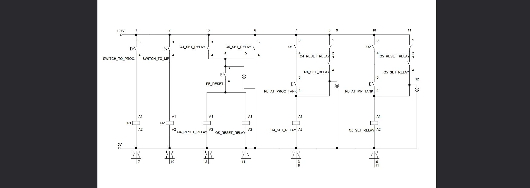
For simple project like this one, I like to use Festo FluidSim to quickly design and simulate control logic before implementation.
Selector switch to Tank A (Proc.) -> Press the pushbutton on the Tank A - > Press the reset button -> Switch off selector switch.
Selector switch to Tank B (MP) -> Press the pushbutton on the Tank B - > Press the reset button -> Switch off selector switch.
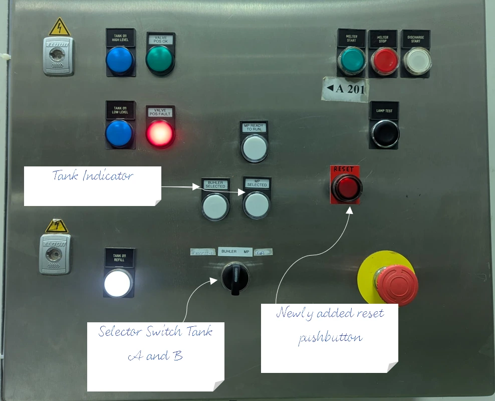
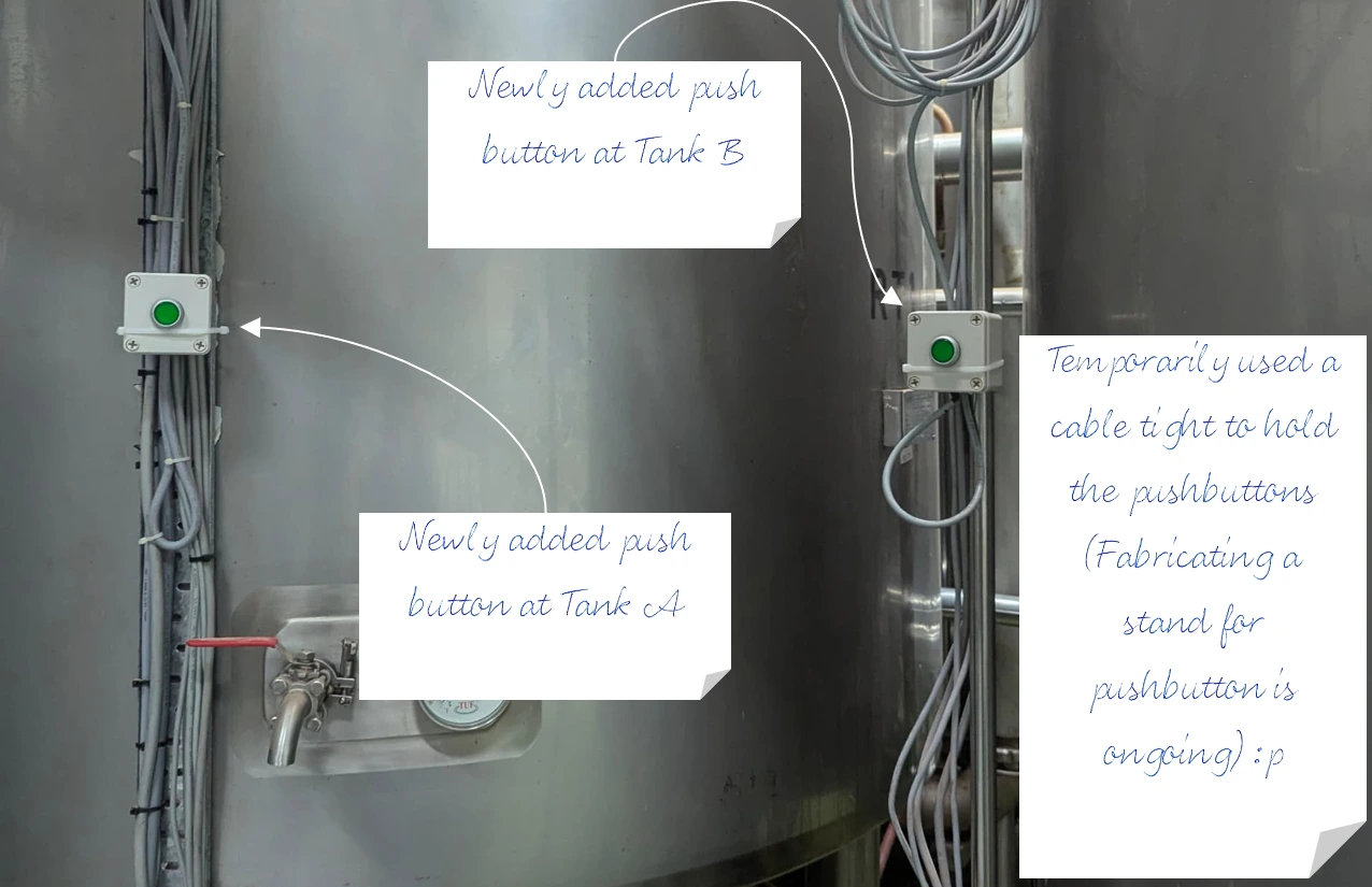
Once the control system design was approved, the next step was to proceed with the wiring. See below for the actual images of the wiring work completed on the tank and the control panel.

The control panel. I would say the most problematic work for this project is drilling that hole for the reset button. Reminder for myself to use carbide holesaw for thicker panel instead of HSS.

The tank area. When in doubt, use cable tight.
